Digital Electronics: Half-Subtractor, De Morgan’s Theorems, 2 to 4 Decoder, JK Flip-Flop, and Flip Flop Types
What is a Half-Subtractor?
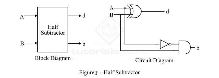
A half-subtractor is a combinational logic circuit that have two inputs and two outputs (i.e. difference and borrow). The half subtractor produces the difference between the two binary bits at the input and also produces a borrow output (if any). In the subtraction (A-B), A is called as Minuend bit and B is called as Subtrahend bit. The block diagram and logic circuit diagram of the half subtractor is shown in Figure-1.
What are De Morgan’s Theorems?
Two of the theorems were suggested by De Morgan that are extremely useful for Boolean Algebra. These two theorems have been discussed below in this article:
Theorem 1
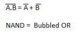
- The LHS (left-hand side) of this theorem represents the NAND gate that has inputs A and B. On the other hand, the RHS (right-hand side) of this theorem represents the OR gate that has inverted inputs.
- The OR gate here is known as a Bubbled OR.
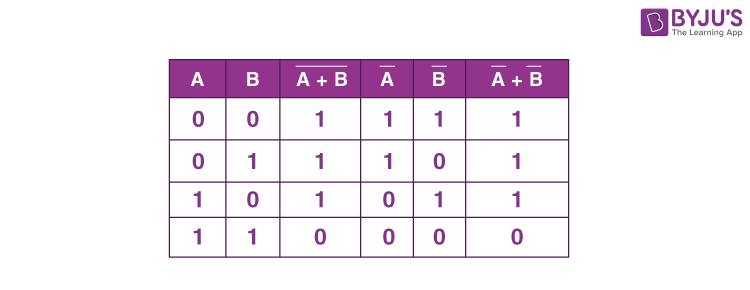
Here is a table that shows the verification of the first theorem of De Morgan:
Theorem 2
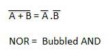
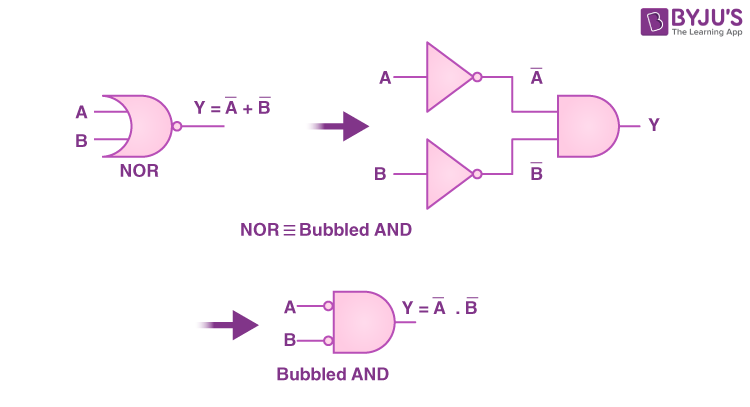
- The left-hand side of this theorem represents the NOR gate that has inputs A and B. On the other hand, the right-hand side represents the AND gate that has inverted inputs.
- The AND gate here is known as a Bubbled AND.
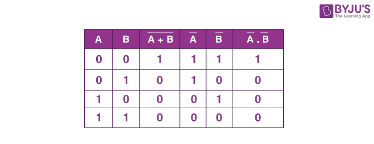
Here is a table that shows the verification of the second theorem of De Morgan:
A 2 to 4 decoder is a combinational logic circuit that takes two input lines, typically labeled A and B, and generates four output lines, usually labeled Y0, Y1, Y2, and Y3. The decoder analyzes the input combination and activates the corresponding output line. Each output line represents a unique combination of the input lines.

The 2 to 4 decoder is called a “2 to 4” decoder because it has two input lines (A and B) and four output lines (Y0, Y1, Y2, and Y3). The number of output lines is determined by the number of input lines, following the formula: 2^n, where n is the number of input lines.
Last Updated on June 16, 2023 by Mayank Dham
In digital electronics, decoders are fundamental building blocks used to convert coded information into a set of distinct outputs. One commonly used decoder is the 2 to 4 decoder, which takes in two input lines and produces four output lines. In this article, we will delve into the concept of a 2 to 4 decoder, understand its functionality, explore its truth table, and discuss its applications.
Introduction to 2 to 4 Decoder
A 2 to 4 decoder is a combinational logic circuit that takes two input lines, typically labeled A and B, and generates four output lines, usually labeled Y0, Y1, Y2, and Y3. The decoder analyzes the input combination and activates the corresponding output line. Each output line represents a unique combination of the input lines.
The 2 to 4 decoder is called a “2 to 4” decoder because it has two input lines (A and B) and four output lines (Y0, Y1, Y2, and Y3). The number of output lines is determined by the number of input lines, following the formula: 2^n, where n is the number of input lines.
Understanding the Truth Table
To understand the functionality of a 2 to 4 decoder, let’s examine its truth table. The truth table shows the output states for all possible input combinations.

What is JK Flip-Flop?
It is one kind of sequential logic circuit which stores binary information in bitwise manner. It consists of two inputs and two outputs. Inputs are Set(J) & Reset(K) and their corresponding outputs are Q and Q’. JK flipflop has two modes of operation which are synchronous mode and asynchronous mode. In synchronous mode, the state will be changed with the clock(clk) signal, and in asynchronous mode, the change of state is independent from its clock signal. Let’s see its diagram structure.

The JK flip flop diagram above represents the basic structure which consists of Clock (CLK), Clear (CLR), and Preset (PR).
d flip flop
A flip flop in digital electronics is a circuit with two stable states that can be used to store binary data. The stored data can be changed by applying varying inputs. Flip-flops and latches are fundamental building blocks of digital electronics systems used in computers, communications, and many other types of systems. Both are used as data storage elements.
It is the basic storage element in sequential logic. But first, let’s clarify the difference between a latch and flip-flops.
Flip Flop Types
There are basically 4 types of flip-flops in digital electronics:
- SR Flip-Flop
- JK Flip-Flop
- D Flip-Flop
- T Flip-Flop
Ex or gate using basic gate