Software Development Life Cycle (SDLC) and UML Diagrams
Explain the Principles of Testing
Testing plays a crucial role in software development by revealing defects and ensuring quality. Here are some key principles of testing:
1. Testing Shows the Presence of Defects
The primary goal of software testing is to identify defects. While it reduces the likelihood of defects, testing cannot guarantee their complete absence. It primarily focuses on revealing their presence, not proving their absence.
2. Exhaustive Testing Is Not Possible
Exhaustive testing, which involves testing all possible inputs and preconditions, is practically impossible due to the vast number of combinations. Instead, testers focus on strategically selecting test cases that cover the most critical aspects of the software.
3. Early Testing
Initiating testing early in the Software Development Life Cycle (SDLC) is essential. Defects detected in earlier phases are less expensive to fix. Ideally, testing should begin during the requirement analysis phase.
4. Defect Clustering
The Pareto Principle applies to software testing, suggesting that a small number of modules often contain most of the defects. Focusing testing efforts on these critical modules can yield significant results.
5. Pesticide Paradox
Repeatedly executing the same test cases may not uncover new defects. To overcome this, it’s crucial to regularly review and update test cases to ensure they remain effective in finding new issues.
6. Testing Is Context-Dependent
The testing approach should be tailored to the specific software being developed. Different types of software require different testing strategies. For example, testing an e-commerce website differs significantly from testing an Android application.
7. Absence of Errors Fallacy
Even if software is 99% bug-free, it can still be unusable if it fails to meet user requirements. It’s crucial to ensure that the software not only functions correctly but also fulfills its intended purpose and satisfies user needs.
The Software Testing Life Cycle (STLC)
The Software Testing Life Cycle (STLC) is a systematic approach to ensuring software quality and minimizing defects. It involves a series of phases, each with specific objectives and deliverables:
Stages of the STLC:
- Test Planning
- Test Analysis
- Test Design
- Test Environment Setup
- Test Execution
- Test Closure
- Defect Retesting
Characteristics of STLC:
- STLC is an integral part of the SDLC, focusing specifically on testing phases.
- STLC begins as soon as requirements are defined or the software requirement document is shared.
- STLC provides a structured process to ensure high-quality software.
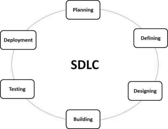
Software Development Life Cycle (SDLC)
The Software Development Life Cycle (SDLC) is a structured methodology for designing, developing, and testing high-quality software. It outlines a step-by-step process to ensure that the final product meets user requirements, is delivered on time and within budget, and is maintainable.
Stages of SDLC:
- Planning and Requirement Analysis
- Defining Requirements
- Designing Architecture
- Developing Product
- Product Testing and Integration
- Deployment and Maintenance of Products

Unified Modeling Language (UML)
Unified Modeling Language (UML) is a standardized visual modeling language used in software engineering to represent the design of a system. It provides a way to visualize the structure and behavior of a system, facilitating communication and understanding among stakeholders.
Types of UML Diagrams:
1. Structural Diagrams
- Class Diagram: Models classes, attributes, and their relationships.
- Object Diagram: Shows instances of classes at a specific point in time.
- Component Diagram: Represents the components of a system and their interrelations.
- Deployment Diagram: Illustrates the physical deployment of artifacts on hardware nodes.
- Package Diagram: Groups related classes or packages.
- Composite Structure Diagram: Shows the internal structure of a class or component.
2. Behavioral Diagrams
- Use Case Diagram: Represents the functional requirements of a system by showing actors and their interactions with the system.
- Sequence Diagram: Depicts the sequence of messages exchanged between objects over time.
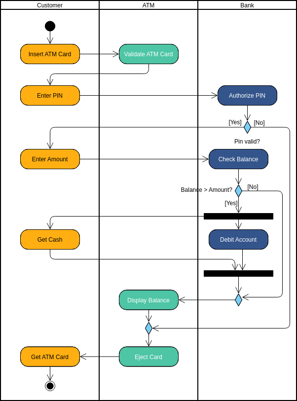
- Activity Diagram: Models workflows and business processes.
- State Machine Diagram: Describes the states an object goes through during its life cycle.
- Communication Diagram: Shows how objects interact in terms of messages and relationships.
3. Interaction Diagrams
- Interaction Overview Diagram: A combination of activity and sequence diagrams that provides an overview of the flow of control.
- Timing Diagram: Depicts changes in state or condition of an object over time.

The Agile View of the Process
The Agile methodology emphasizes adaptability, iterative progress, and collaboration over rigid, linear planning. It focuses on delivering software in small, functional increments called “iterations” or “sprints,” typically lasting 1-4 weeks. This allows for frequent feedback and adjustments based on stakeholder needs.
Key Points of Agile:
- Iterative Development: Small, incremental updates.
- Customer Collaboration: Close engagement with stakeholders for feedback.
- Flexibility: Adapts easily to changes in requirements.
- Teamwork: Cross-functional, self-organizing teams.
- Continuous Improvement: Focuses on learning and refining the process after each sprint.
- Frequent Delivery: Ensures regular, working product releases.
Negotiating and Validating Requirements
Negotiating Requirements
Negotiating requirements involves reconciling differing viewpoints and priorities among stakeholders. The goal is to find a balance between desired features and project constraints, ensuring everyone’s expectations align.
Validating Requirements
Validating requirements ensures that they accurately reflect stakeholder needs and are feasible to implement. Techniques like prototyping and user testing help confirm that the requirements will result in a valuable product.
The Taxonomy of Architectural Design
The taxonomy of architectural design in software engineering provides a structured classification of components and principles for designing a system’s architecture. It addresses aspects like modularity, abstraction, architectural styles (e.g., Layered Architecture, Microservices Architecture), and non-functional requirements (e.g., security, performance).
Developing a Diagram in UML
Developing a UML diagram involves creating a visual representation of a system’s structure or behavior. For example, a Class Diagram can illustrate the classes and relationships in an online shopping system.
Example: Class Diagram for Online Shopping System
1. Identifying Classes
Examples of classes in an online shopping system:
- Customer
- Order
- Product
- Shopping Cart
- Payment
2. Defining Attributes and Methods
Each class has attributes (data) and methods (functions). For example:
Customer:
- Attributes: customerID, name, email
- Methods: register(), login(), logout()
Order:
- Attributes: orderID, orderDate, status
- Methods: createOrder(), cancelOrder()
3. Establishing Relationships
Relationships between classes are defined, such as association (e.g., a customer can place multiple orders) and aggregation (e.g., a shopping cart contains multiple products).
